General Information

G-0001 Procedure for Spare Parts Ordering

Procedure for Spare Parts Ordering

Generally, Tokyo Keiso Products are so called Order Made products and they are designed and fabricated according to each customer's operating conditions/specifications. Thus, the spare parts for our products may be different even for products with the same model code.

All our products are managed and controlled by our Manufacturing Number. When ordering spare parts, the Manufacturing Number of the original main order (henceforth designated as Old Manufacturing Number) and the required parts name must be specified.

Location of Manufacturing Number

The manufacturing number can be confirmed by any of the following methods.

  • Confirmed from the "Product Specifications" document. (The manufacturing number is described as the manufacturing number or MFG.NO.)
  • Described on the name plate or sticker attached to the product.
  • If there is no name plate,
    it is engraved on the scale plate, glass taper tube, and the outer peripheral part of the flange.

Example of manufacturing number

F20 - □□□□□□ – 1
L99 - □□□□□□

On our Manufacturing Number

The Manufacturing Number is specified as following :

Product group identification * Product group
F Flow meters
ES Flow meters
CF Coriolis flow meter
EF Electromagnetic Flow meters
UF Ultrasonic Flow meters
L Level Instruments

* Other symbols may be used.

G-0002 Description on Material JIS-ASTM

Description on Material JIS-ASTM

This is to indicate the equivalent metallic material in JIS standard and ASTM standard. However, it is to be noted that this is reference only for users' convenience and there might be differences in detailed composition etc.

1. PIPE
Material
Description
ASTM Standard JIS Standard Remarks
Carbon Steel A135 Gr.A G 3454 STPG 370  
A53 Gr.E-A  
A135 Gr.B STPG 410  
A53 Gr.E-B  
A53 Type F G 3452 SGP  
A106 Gr.A G 3456 STPT 370  
Gr.B STPT 410  
A333 Gr.1 G 3460 STPL 380  
Gr.3 STPL 450  
Stainless Steel A312 Gr.TP304 G 3459 SUS 304TP  
Gr.TP304L SUS 304LTP  
Gr.TP316 SUS 316TP  
Gr.TP316L SUS 316LTP  
2. FORGING MATERIAL
Material
Description
ASTM Standard JIS Standard Remarks
  A105 - G 3201 SF 490A  
  - G 3202 SFVC 2A  
  A181 Gr.I G 4051 S25C (Forging)  
  Gr.II S30C (Forging)  
  A350 Gr.LF2 G 3205 SFL2  
  A182 Gr.F1 G 3203 SFVA F1  
  Gr.F2 SFVA F2  
  A182 Gr.F304 G 3214 SUS F304  
  Gr.F316 SUS F316  
  Gr.F316L SUS F316L  
3. CASTING MATERIAL
Material
Description
ASTM Standard JIS Standard Remarks
Cast Steel A216 Gr.WCA G 5151 SCPH1  
Gr.WCB SCPH2  
A352 Gr.LCB G 5152 SCPL1  
Cast Stainless
Steel
A351 Gr.CF-8 G 5121 SCS13A  
Gr.CF-8M SCS14A  
Gr.CF-3M SCS16A  
Cast Iron A48 Class No.30 G 5501 FC 200  
A126 Class B FC 200  
A48 Class No.35 G 5501 FC 250  
A126 Class C FC 250  
Malleable Iron A197   G 5702 FCMB 270  
A47M Gr.22010 FCMB 340  
A47 Class 32510  
Ductile Iron A536 Gr.60-40-18 G 5502 FCD 400-15  
Gr.65-45-12 FCD 450-10  
4. PLATE,BAR
Material
Description
ASTM Standard JIS Standard Remarks
Plates and Bars A283 Gr.C G 3101 SS 400  
Gr.D G 3101 SS 400  
Plate A109   G 3141 SPCC  
Plates and Bars Plate: A167
Bar: A276
Wire: A313
S30400
(TYPE 304)
Plate: G4304
Bar: G4303
Wire: G4308
SUS 304  
S30403
(TYPE 304L)
SUS 304L  
S31600
(TYPE 316)
SUS 316  
S31603
(TYPE 316L)
SUS 316L  
Bar A576 Gr.1025 G4051 S25C  
5. BOLT & NUT
Material
Description
ASTM Standard JIS Standard Remarks
  A307 Gr.B G 3101 SS 400 Bolt
  A563 Gr.A G 3101 SS 400 Nut
  A193 Gr.B7 G 4107 SNB7 Bolt
  A194 Gr.2H G 4051 S45C Nut
  A193 Gr.B8 G 4303 SUS 304 Bolt
  Gr.B8M G 4303 SUS 316 Bolt
  A194 Gr.8 G 4303 SUS 304 Nut
  Gr.8M G 4303 SUS 316 Nut
  - - G4105 SCM435 Bolt
6. ALUMINIUM,BRASS

Material
Description

ASTM Standard

JIS Standard

Remarks
Aluminum Die-casting B85 383.0 H 5302 ADC 12Z  
Aluminum Casting B26 319.0(-) H 5202 AC 2B
(AC 2A)
 
Aluminum Alloy B221 6063 H 4100 A6063(S)  
B221 6063 H 4040 A6063(BE)  
Brass B16 C36000 H 3250 C3604(B)  

[Referred Documents]
JIS Metallic Material Hand Book Rev.4
JIS Hand Book Steel, Non-Steel
Others

G-0004 2-wire DC 4-20 mA Analog Output

We are often asked for the relation between flow rate and analog output (DC 4-20 mA) of flowmeter. This is an easy explanation of such analog output.

At analog output type flowmeters the flow rate value is converted to electric current and transmitted.

The output current is designed so that 4 mA corresponds to 0% of full scale range of the flowmeter and 20 mA corresponds to 100% of full scale range of the flowmeter irrespective of absolute flow rate. The change of current output is linear to the flow rate change.

For example, when the scale range of flowmeter is designed as 0-30 m3/h, the output current will be;

Percentage of full scale Actual flow rate Current output figure
0% 4 mA  
10% 3 m3/h 5.6 mA
50% 15 m3/h 12 mA
100% 30 m3/h 20 mA

This is indicated by the following graph.

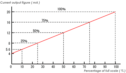
When the load resistance of the circuit is within the limited figure, the output current which is proportional to the flow rate is obtained irrespective of the load resistance. Practically, the power supply line (normally, DC 24 V) and signal current line are common. For indication, a current meter, on which 100% is graduated at 20 mA point and 0% at 4 mA, is connected serial in such signal line.

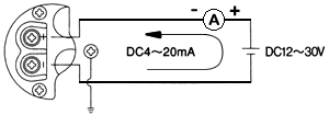
Wiring diagram of AM-1520 type variable area flowmeter is shown for reference.

Contact usProduct Inquiry

We will answer your product inquiries and technical questions.