-
FlowMeasurement
-
LevelMeasurement
-
Related Instruments
Guidance Download
QR code
* Please scan the QR code with your smartphone to access this website page.
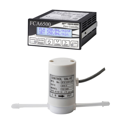
The FC6500 series is a separate-type flow control system that captures flow signals from various sensors in analog form and controls valves to stabilize the flow rate at the target value. It consists of a control valve, of which the wetted parts are made of fluorocarbon resin, and a flow controller.
· Flow control valve: FCV series
· Flow controller: FCA6500 series
The FC6500 series can control a wide range of flow rates with an extensive lineup of control valves. Its design with physically separated control valve and control unit enhances safety and layout flexibility.
The FC6500 series is ideal for process management of chemical liquids and deionized water in semiconductor and other manufacturing processes.
Besides flow rate, the FC6500 series can also be used as a temperature or pressure control system by regulating the flow control valve.
The flow detector and the control valve in the process fluid part are separated from the measurement and control part, ensuring enhanced protection against liquid leakage as well as greater layout flexibility.
The FCV series control valves can cover a wide range of flow rates, from a minimum of 10 to 100 mL/min up to 1 to 10 L/min.
Complies with EU EMC, RoHS2, and low voltage requirements
(EMC standards: EN61326-1: 2013, EN61326-2-3: 2013)
Model | FCV-1000S | FCV-3000 |
---|---|---|
Nominal diameter | Φ3/8”, Φ1/2” | Φ1/4” |
Flow range | Max. 10 L/min Min. 200 mL/min |
Max. 2 L/min Min. 2.5 mL/min |
Fluid Temperature | 5 to 50 ℃ | |
Fluid Pressure | 0.3MPa | |
Process Connection | PTFE, PFA |
Model | FCA6510 | FCA6520 | FCA6530 |
---|---|---|---|
Analog input (Current flow rate) |
4 to 20 mA DC Input impedance: 250 Ω |
0 to 10 V DC Input impedance: 730 kΩ |
4 to 20 mA DC Input impedance: 250 Ω |
Digital input (Change of control) |
Non-voltage contact input Close ON: Start control, Open OFF: Stop control |
||
Analog output (Flow rate re-output) |
1 to 5 V DC Allowable load resistance: 500 kΩ or higher |
0 to 10 V DC Allowable load resistance: 500 kΩ or higher |
4 to 20 mA DC Allowable load resistance: 500 Ω or lower |
Digital output (Alarm) |
Open collector output (rated value: 30 V DC, 50 mA) Logic: A (NO)/B (NC) set at the factory |
||
Control accuracy |
Flow rate (PV) > 30%FS: ±3% of the target value (SP) Flow rate (PV) ≦ 30%FS: ±5% of the target value (SP) Response time within 3 seconds * Analog inputs from detectors must be updated without delay. |
||
Display |
2 lines, 16 alphanumeric letters LCD with a backlight Alarm: red (LED), status: green (LED) |
||
Construction/ Installation |
Indoor use (IP 20 equivalent), panel mount | ||
Power supply | 24 V DC ±10% |
FlowMeasurement
LevelMeasurement
Related Instruments
Guidance Download
* Please scan the QR code with your smartphone to access this website page.