QR code
* Please scan the QR code with your smartphone to access this website page.
Variable area flowmeters (Rotameters) theoretically involve indication errors when the operating condition deviate from the design condition. However, these errors can be compensated by calculations.
The calculation procedure by fluid types are shown below.
The liquid density change from the design condition produces indication error.
Actual Flow rate = Indicated flow rate × Correction coefficient
![]()
![]()
Density correction coefficient
![]()
Design density (g/cm3)
to be referred to Approval drawing
![]()
Density of the measuring liquid (g/cm3)
the density of actual liquid
![]()
Density of float (g/cm3)
differs by material, Refer to the following table.
| Float material | Density of float * |
|---|---|
| Stainless steel | 7.7 g/cm3 |
| PVC | 2.7 g/cm3 |
* Figures may have deviations due to final design.
Original design condition of flowmeter
Fluid : Water
Design density : 1.0 g/cm3
Actual process condition
Fluid : Alcohol
Actual density : 0.8 g/cm3
Indication of flowmeter : 10m3/h

Actual flow rate of Alcohol = 10 × 1.134 = 11.34 m3/h
In Gas Flow Measurement,
Density of the gas to be measured (under Normal condition, 0°C,1atm)
Operating pressure
Operating temperature
as the factors of compensation.
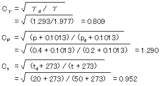
· Density compensation
![]()
![]()
Density correction coefficient
![]()
Design density [kg/m3(nor)]
to be referred to Approval drawing
![]()
Density of the gas to be measured [kg/m3(nor)]
· Pressure compensation
![]()
![]()
Pressure correction coefficient
![]()
Design pressure (MPa)
in Gauge pressure,to be referred to Approval drawing
![]()
Actual operating pressure (MPa)
in Gauge pressure
· Temperature correction
![]()
![]()
Temperature correction coefficient
![]()
Design temperature(°C)
to be referred to Approval drawing
![]()
Actual operating temperature(°C)
Original design condition of flowmeter
Fluid : Air
Design density : 1.293 kg/m3(nor)
Design pressure : 0.2 MPa
Design temperature : 20°C
Actual process condition
Fluid : CO2 Gas
Design density : 1.977 kg/m3(nor)
Actual operating pressure : 0.4 MPa
Actual operating temperature : 50°C
Indication of flowmeter : 5m3/h(nor)

![]()
Actual flow rate of CO2 gas = 5 × 0.994 = 4.97 m3/h(nor)
Correction calculation is done by the density of the steam to be measured
Actual Flow rate = Indicated flow rate × Correction coefficient
![]()
![]()
Density correction coefficient
![]()
Density of actual steam (kg/m3)
![]()
Design density (kg/m3)
Original design condition of flowmeter
Fluid : Steam
Design density : 5.163 kg/m3
Design pressure : 0.902 MPa
Design temperature : 180°C
Actual process condition
Fluid : Steam
Design density : 2.549 kg/m3
Actual operating pressure : 0.3479 MPa
Actual operating temperature : 150°C
Indication of flowmeter : 10 t/h
The steam density in operating condition is to be referred to Steam Table.

Actual Flow rate at 150°C = 10 t/h × 0.703 = 7.03 t/h
* Please scan the QR code with your smartphone to access this website page.